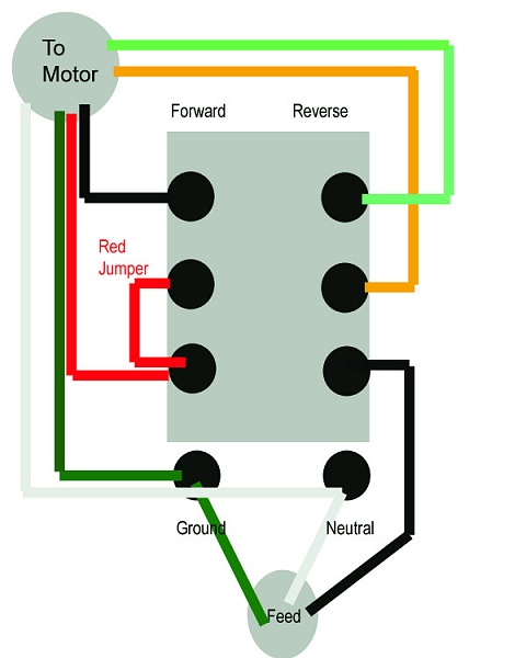
Motor control wiring diagram Motor control circuit diagram wiring simple latching contactor switch diagrams contact instrumentation auxiliary float previous next tools instrumentationtools Dc motor speed control project
Ac Motor Control Diagram ~ Ac Motor Kit Picture
File:wiring diagram of motor control centre on pump station.jpg Two speeds, two directions multispeed 3-phase motor power & control Directions speed diagrams speeds multispeed electricaltechnology lead
Ac motor control diagram ~ ac motor kit picture
Wiring motor dayton diagram control speed hp electric motors 115v boat model lift ao smith schematic circuit quit open wiringallWiring fixya Motor dc control speed diagram project circuit block controller using regenerative braking wiring electronic unit connection scr ponent seekic icControl motor wiring diagram pump centre station file commons.
Wiring diagram for a dayton 4x796 motor speed control .

Two Speeds, Two Directions Multispeed 3-phase Motor Power & Control

DC Motor Speed Control Project

Wiring Diagram For A Dayton 4x796 Motor Speed Control

Ac Motor Control Diagram ~ Ac Motor Kit Picture

Motor Control Wiring Diagram - 4K Wallpapers Review